

 English
 Deutsch
 Español
 русский

Home · News · Industry News · What Is a Toolless Plug and Why It Revolutionizes Network Cabling?
Industry News
What Is a Toolless Plug and Why It Revolutionizes Network Cabling?
2026-05-08Content
- 1 Technical Principles: How Reliable Connections Are Achieved Without Tools
- 2 Performance Comparison: Toolless Termination vs. Traditional Crimping
- 3 Application Scenarios
- 4 Selection Guide
- 5 Installation Essentials: Key Steps to Ensure First-Time Success in Toolless Termination
- 6 Development Trends: Future Evolution of Toolless Termination Technology
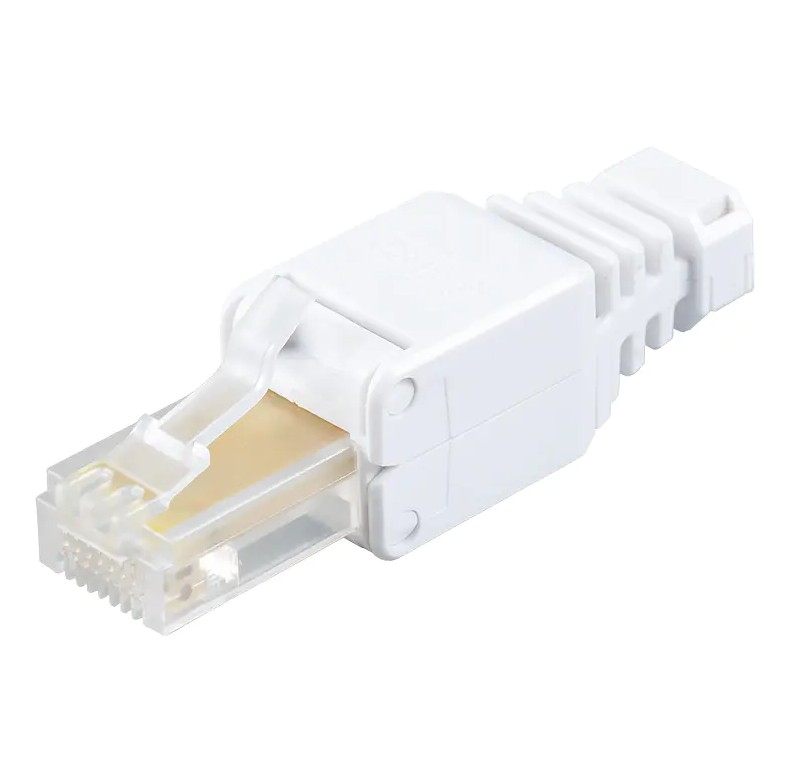
A Toolless Plug is a connector that completes network cable termination without requiring specialized tools such as crimping pliers or cable strippers. Its core advantage lies in shortening the traditional professional crimping process from 3–5 minutes to just 30–60 seconds, while reducing dependency on operator skill levels. In data centers, smart buildings, and industrial automation scenarios, adopting toolless termination technology can improve overall cabling efficiency by more than 40% and reduce contact failure rates caused by improper operation from 8%–12% (traditional method) to below 2%.
Technical Principles: How Reliable Connections Are Achieved Without Tools
Traditional RJ45 plugs rely on metal crimping tools to press eight copper conductors into blades and cut off excess wires simultaneously. Toolless Plugs achieve equivalent electrical performance and mechanical strength through innovative mechanical structures.
Evolution of Insulation Displacement Connection (IDC) Technology
Toolless plugs employ enhanced IDC technology with precision dual-edge blades inside. After inserting the cable wires arranged according to T568A/B standards, termination is completed through the following two methods:
- Push-down type: Pressure is applied directly through a top cover on the housing, pressing the conductors into the blades and cutting off excess. This is suitable for Cat5e/Cat6 unshielded models.
- Screw/Twist-lock type: A rear nut is rotated to drive an internal pressing block forward, gradually compressing the conductors. This is commonly found in Cat6A/Cat7/Cat8 shielded models and provides stronger pull-out resistance (typically ≥50N).
Ensuring Shielding Integrity
For shielded twisted pair (STP/FTP) applications, toolless plugs feature metal housings combined with rear grounding clamps. This联动 design ensures 360-degree full contact of the shielding layer. Taking the Cat6A shielded type as an example, the metal compression ring automatically tightens and pierces the cable's outer shielding layer while the rear nut is being tightened, achieving grounding continuity with transfer impedance controlled below 50mΩ, meeting the shielded link requirements of the ISO 11801 standard.
Performance Comparison: Toolless Termination vs. Traditional Crimping
Although the operation methods differ, qualified Toolless Plugs match or even exceed traditional crimp plugs in electrical performance. The following table compares key parameters:
| Comparison Item | Toolless Plug (Cat6A Shielded) | Traditional Crimp Plug (Cat6A Shielded) |
|---|---|---|
| Termination Time | 30–60 seconds | 3–5 minutes |
| Tools Required | No specialized tools needed | Crimping tool, stripper, cable tester |
| Insertion Loss (100MHz) | ≤0.1dB | ≤0.15dB |
| Return Loss (100MHz) | ≥26dB | ≥24dB |
| Pull-out Resistance | ≥50N | ≥30N |
| Re-termination Cycles | 2–3 times | 1 time (plug replacement required) |
| Skill Requirement | Low (insert by color code) | High (requires crimping force and angle control) |
As shown in the table, toolless plugs outperform traditional crimping in both insertion loss and return loss. This is attributed to the integrated precision machining of internal blades, which eliminates contact resistance fluctuations caused by uneven manual crimping force.
Application Scenarios
Data Centers and Server Rooms
In data centers with thousands of information points, cabling density is extremely high and space is limited. Using Toolless Plugs can increase a single technician's daily termination capacity from 50–80 units to 150–200 units. More importantly, the toolless design allows direct operation at the rear of cabinets or within cable trays without needing space for crimping tools, significantly reducing maintenance downtime for in-service systems.
Smart Buildings and Structured Cabling
Commercial office building cabling systems often require construction within confined spaces such as ceiling plenums and floor ducts. The compact design of toolless plugs (some models are only 40–45mm in length), combined with rear strain relief structures, enables termination directly in tight spaces. This avoids wire sequence errors or poor crimping caused by insufficient operating space inherent in traditional methods.
Industrial Sites and Temporary Network Deployment
In factory automation, exhibition construction, or emergency communication scenarios, network topologies frequently require temporary adjustments. The re-terminable feature of toolless plugs (allowing 2–3 re-wiring cycles) makes them ideal for mobile equipment and temporary links. Meanwhile, shielded models with metal housings effectively resist electromagnetic interference (EMI) in industrial environments, ensuring stable Gigabit/10-Gigabit transmission even near frequency converters and motors.
Selection Guide
Toolless Plugs available on the market are divided into multiple series based on performance grade, shielding type, and locking mechanism. Improper selection will directly affect link performance and service life.
Matching by Network Grade
- Cat5e (Enhanced Category 5): Suitable for 100Mbps to 1Gbps networks. Unshielded push-down types are sufficient and offer the lowest cost.
- Cat6 (Category 6): Supports 1Gbps to 10Gbps (short distances). Winged push-down structures are recommended to enhance cable retention force.
- Cat6A (Augmented Category 6): 10Gbps standard transmission distance reaches 100 meters. Full metal shielded housings with twist-lock rear sections are mandatory to control alien crosstalk.
- Cat7/Cat8 (Category 7/8): Designed for 25G/40G and higher speeds. Full-shielded metal buckle structures are required, with rear nuts achieving shielding layer grounding to ensure end-to-end shielding continuity.
Matching by Cable Type
Different outer diameter cables require matching toolless plugs with corresponding wire gauge ranges. Common specifications are as follows:
- Standard round cable (OD 5.5–6.5mm): Select standard rear bore diameter models
- Slim patch cord (OD 4.0–5.0mm): Choose slim-wire compatible models to avoid loose crimping
- Extra-heavy industrial cable (OD 7.0–9.0mm): Select large-bore rear sections with reinforced strain relief structures
Installation Essentials: Key Steps to Ensure First-Time Success in Toolless Termination
Although the toolless design lowers the operational threshold, following standardized procedures is still essential to ensure long-term reliability.
- Precise Stripping Length Control: Strip the outer jacket to the length marked on the plug (typically 12–15mm). Maintain the twisted state until the moment before insertion to avoid excessive untwisting that causes Near-End Crosstalk (NEXT) exceedance.
- Strict Color Code Sequencing: Whether using T568A or T568B standards, ensure all eight conductors are completely straight and arranged in order. Some high-end toolless plugs feature transparent wire channels for visual confirmation of each conductor's position.
- Insert Completely in One Motion: Insert the arranged wire bundle vertically into the plug until each conductor reaches the internal stop. For twist-lock types, confirm the wire bundle has not retracted before tightening.
- Apply Sufficient Pressure: For push-down types, apply even pressure with fingers or the palm heel; an audible "click" indicates the cover is fully seated. For twist-lock types, tighten the rear nut in the indicated direction until significant resistance is felt, typically requiring 3–5 turns.
- Verification and Testing: After termination, always use a cable certification tester for continuity, crosstalk, and return loss testing. For shielded models, use a multimeter to verify conductivity between the shielding layer and the plug's metal housing.
Common Failure Warning: Approximately 60% of toolless termination failures result from excessive stripping length exposing too much untwisted wire pairs, or incorrect wire sequences forced into crimping. Since toolless blades are typically sharper than traditional plugs, conductor damage from incorrect termination is irreversible. The cable must be re-cut before re-attempting.
Development Trends: Future Evolution of Toolless Termination Technology
As PoE++ (IEEE 802.3bt) power delivery increases to 90W, and Single Pair Ethernet (SPE) gains traction in Industrial IoT, Toolless Plugs face new technical challenges and upgrade directions.
High-Power PoE Compatibility Optimization
High current passing through contact points generates Joule heating, increasing contact resistance. New-generation toolless plugs adopt high-conductivity phosphor bronze gold-plated contacts (gold plating thickness increased from the traditional 3μin to 6–10μin) and enlarge IDC blade contact areas. This controls temperature rise within 15°C, meeting the reliability requirements for long-term 90W PoE operation.
Modular and Integrated Design
Some manufacturers have already introduced toolless plugs with integrated LED indicators. After termination is complete, light colors directly display wire sequence correctness (green) or errors (red), reducing on-site testing time by another 50%. Additionally, toolless adapter solutions compatible with M12 industrial connectors are emerging, aiming to bridge the physical layer boundary between office networks and industrial fieldbuses.
Contact Us
Your email address will not be published. Required field are marked*


-
 No. 588, Xiaolin Avenue, Xiaolin Town, Cixi City, Zhejiang Province
-
 [email protected]
-
 +86-574-63507962
-
 +86-15988643730
Copyright Ningbo Betterbell Telecommunication Equipment Co., Ltd. All rights reserved. Structured Cabling Solutions Manufacturer Network Cabling Products Supplier
